Product Description
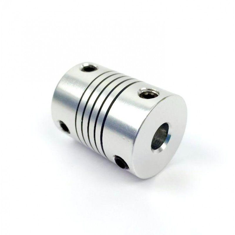
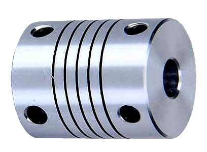
SC Transmission FCL Flexible Shaft Couplings for Reducer and Motor
Product Description
FCL Coupling/Shaft Coupling /Pin & Bush Coupling /FCL Flexible Coupling/NBK FCL Coupling is widely used for its compacts designing, easy installation, convenient maintenance, small and light weight.
As long as the relative displacement between shafts is kept within the specified tolerance, couplings will operate the best function and have a longer working life.
Thus it is greatly demanded in medium and minor power transmission systems driven by motors, such as speed reducers, hoists, compressors, conveyors, spinning and weaving machines and ball mills.
Product Parameters
| SIZE | D | D1 | d1 | L | C | n-M | kg | |||
| r/min | ||||||||||
| N.m | ||||||||||
| FCL90 | 4 | 4000 | 90 | 35.5 | 11 | 28 | 3 | 4-M8 | 1.7 | |
| FCL100 | 10 | 4000 | 100 | 40 | 11 | 35.5 | 3 | 4-M10 | 2.3 | |
| FCL112 | 16 | 4000 | 112 | 45 | 13 | 40 | 3 | 4-M10 | 2.8 | |
| FCL125 | 25 | 4000 | 125 | 65 | 50 | 13 | 45 | 3 | 4-M12 | 4 |
| FCL140 | 50 | 4000 | 140 | 71 | 63 | 13 | 50 | 3 | 6-M12 | 5.4 |
| FCL160 | 110 | 4000 | 160 | 80 | 15 | 56 | 3 | 8-M12 | 8 | |
| FCL180 | 157 | 3500 | 180 | 90 | 15 | 63 | 3 | 8-M12 | 10.5 | |
| FCL200 | 245 | 3200 | 200 | 100 | 21 | 71 | 4 | 8-M20 | 16.2 | |
| FCL224 | 392 | 2850 | 224 | 112 | 21 | 80 | 4 | 8-M20 | 21.3 | |
| FCL250 | 618 | 2550 | 250 | 125 | 25 | 90 | 4 | 8-M24 | 31.6 | |
| FCL280 | 980 | 2300 | 280 | 140 | 34 | 100 | 4 | 8-M24 | 44 | |
| FCL315 | 1568 | 2050 | 315 | 160 | 41 | 112 | 4 | 10-M24 | 57.7 | |
| FCL355 | 2450 | 1800 | 355 | 180 | 60 | 125 | 5 | 8-M30 | 89.5 | |
| FCL400 | 3920 | 1600 | 400 | 200 | 60 | 125 | 5 | 10-M30 | 113 | |
| FCL450 | 6174 | 1400 | 450 | 224 | 65 | 140 | 5 | 12-M30 | 145 | |
| FCL560 | 9800 | 1150 | 560 | 250 | 85 | 160 | 5 | 14-M30 | 229 | |
| FCL630 | 15680 | 1000 | 630 | 280 | 95 | 180 | 5 | 18-M30 | 296 | |
Company Profile
FAQ
Shipping
/* January 22, 2571 19:08:37 */!function(){function s(e,r){var a,o={};try{e&&e.split(“,”).forEach(function(e,t){e&&(a=e.match(/(.*?):(.*)$/))&&1
Can Motor Couplings Compensate for Angular, Parallel, and Axial Misalignments?
Yes, motor couplings are designed to compensate for different types of misalignments, including angular, parallel, and axial misalignments. The ability to accommodate misalignment is a key feature of motor couplings, and various coupling types offer different levels of misalignment compensation:
1. Angular Misalignment:
Angular misalignment occurs when the motor and driven equipment shafts are not perfectly aligned in the same plane, causing an angle between them. Motor couplings, especially flexible couplings, can effectively compensate for angular misalignment. Flexible couplings like jaw couplings, beam couplings, and oldham couplings can tolerate angular misalignment to a certain extent while transmitting torque smoothly.
2. Parallel Misalignment:
Parallel misalignment happens when the motor and driven equipment shafts are not perfectly aligned along their axis, leading to offset displacement. Flexible couplings, such as bellows couplings and disc couplings, are well-suited to accommodate parallel misalignment. These couplings can maintain good misalignment tolerance while providing high torsional stiffness for efficient torque transmission.
3. Axial Misalignment:
Axial misalignment occurs when there is a linear offset between the motor and driven equipment shafts along the axis. For some flexible couplings, a limited amount of axial misalignment can be tolerated. However, specific coupling types, such as self-aligning ball bearing couplings, are more suitable for handling higher levels of axial misalignment.
It is important to note that while motor couplings can compensate for misalignment, they have their limits. Excessive misalignment can lead to premature wear, reduced efficiency, and potential coupling failure. Proper alignment during installation and regular maintenance are essential to ensure the coupling’s misalignment compensation remains effective over time.
When selecting a motor coupling, consider the type and amount of misalignment expected in your application. Choose a coupling that offers the required level of misalignment compensation, ensuring smooth power transmission and extending the lifespan of the coupling and connected components.
“`
Specific Safety Precautions When Working with Motor Couplings
Working with motor couplings involves handling mechanical components and power transmission systems, which can pose certain safety risks. It is essential to follow specific safety precautions to prevent accidents and ensure the well-being of personnel. Here are some safety measures to consider:
1. Lockout/Tagout Procedures:
Prior to any maintenance or installation work on motor couplings, follow lockout/tagout procedures to isolate the power source and prevent accidental startup. This ensures the motor and equipment are de-energized, reducing the risk of electrical hazards.
2. Personal Protective Equipment (PPE):
Wear appropriate personal protective equipment, including safety goggles, gloves, and steel-toed shoes, when working with motor couplings. PPE provides protection against potential hazards such as flying debris or pinch points.
3. Proper Lifting Techniques:
When handling heavy couplings or equipment, use proper lifting techniques to avoid strain or injury. Seek assistance if needed to lift and position larger components safely.
4. Inspect Coupling Condition:
Before any work, inspect the coupling for signs of wear, damage, or misalignment. Do not work with a damaged coupling, as it may compromise system integrity and safety.
5. Avoid Excessive Force:
Avoid applying excessive force or using tools that are not appropriate for the job when installing or removing couplings. Excessive force can lead to component failure or personal injury.
6. Follow Manufacturer Guidelines:
Adhere to the manufacturer’s guidelines and instructions during installation, maintenance, and troubleshooting processes. Manufacturer recommendations are designed to ensure safe and proper operation.
7. Regular Inspection and Maintenance:
Implement regular inspection and maintenance schedules for motor couplings and associated equipment. Identify and address any issues promptly to prevent potential hazards or failures.
8. Keep Work Area Clean:
Keep the work area clean and free of clutter. A tidy workspace reduces the risk of accidents and improves overall efficiency.
9. Avoid Contact with Rotating Components:
When the motor is energized, avoid contact with rotating coupling components to prevent injury. Ensure the system is de-energized during maintenance tasks.
10. Training and Competence:
Ensure that personnel working with motor couplings are adequately trained and competent in the procedures and safety measures related to coupling installation, maintenance, and operation.
By following these safety precautions, you can minimize risks and create a safer working environment when handling motor couplings and associated power transmission systems.
“`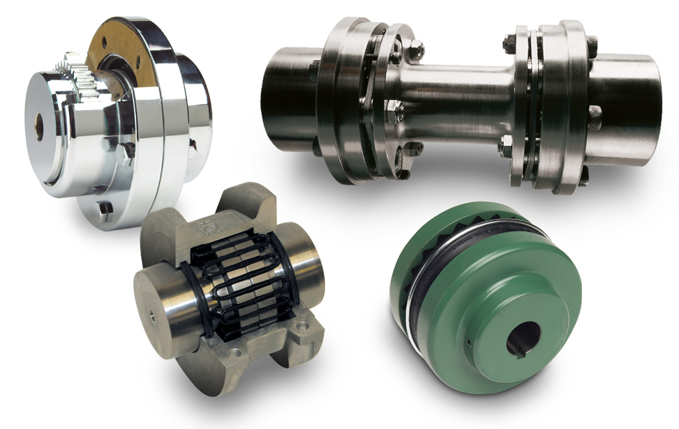
Types of Motor Couplings and Their Applications in Different Industries
Motor couplings come in various types, each designed to meet specific requirements and applications in different industries. Here are some common types of motor couplings and their typical uses:
1. Rigid Couplings:
Rigid couplings provide a solid and inflexible connection between the motor shaft and the driven equipment. They are ideal for applications where precise alignment and torque transmission are critical. Rigid couplings are commonly used in machine tools, robotics, and high-precision industrial equipment.
2. Flexible Couplings:
Flexible couplings are designed to accommodate misalignment between the motor and driven equipment shafts. They can handle angular, parallel, and axial misalignment, reducing stress on bearings and increasing the system’s flexibility. Flexible couplings find applications in pumps, compressors, conveyors, and other machinery where misalignment may occur due to vibration or thermal expansion.
3. Gear Couplings:
Gear couplings use toothed gears to transmit torque between the motor and the driven equipment. They provide high torque capacity and are suitable for heavy-duty applications, such as steel rolling mills, cranes, and marine propulsion systems.
4. Disc Couplings:
Disc couplings use thin metal discs to transmit torque. They offer high torsional stiffness, allowing precise motion control in applications like servo systems, CNC machines, and robotics.
5. Jaw Couplings:
Jaw couplings use elastomeric elements to dampen vibrations and accommodate misalignment. They are commonly used in small electric motors and general-purpose machinery.
6. Bellows Couplings:
Bellows couplings have a flexible accordion-like structure that compensates for misalignment while maintaining torsional rigidity. They are used in vacuum systems, optical equipment, and other high-precision applications.
7. Grid Couplings:
Grid couplings use a flexible grid element to transmit torque and dampen vibrations. They are suitable for applications in pumps, compressors, and conveyor systems where shock loads and misalignment are common.
8. Magnetic Couplings:
Magnetic couplings use magnetic fields to transmit torque between the motor and driven equipment. They are commonly used in applications requiring hermetic sealing, such as pumps and mixers handling hazardous or corrosive fluids.
Each type of motor coupling offers unique advantages and is chosen based on the specific needs of the industry and the application. Proper selection and installation of the right coupling type enhance efficiency, reliability, and safety in motor-driven systems across various industries.
“`

editor by CX 2024-05-03
by
Tags:
Leave a Reply