Product Description
Product Description
|
Product Name |
Fasteners |
|
Standard |
ISO 4017. DIN933 DIN931 DIN934 DIN912 DIN603 DIN6923,GB5783,ASTM,ANSI,JIS, BS |
|
Bolts Diameter |
M2 – M100 |
|
Length(mm) |
5-5000mm |
|
Bolts Head Type |
Hex, Square, Round, Hex flange, Flat, T-head & Triangular etc |
|
Surface Treatment |
Zinc Plated (Yellow, White, Blue, Black), Hop Dip Galvanized (HDG) phosphorization, Black Oxide, Geomet, Dacroment, anodization, Nickel plated, Zinc-Nickel plated, Brass Plated, Tin Plated, Black Plated, Copper Plated, Gold Plated, Salt fog test |
|
Manufacturing Process |
Wire Drawing, Cold Heading, Insert tapping, Heat Treatment, Surface Plating, Inspection, Packing |
|
Tolerance |
+/-0.01mm to +/-0.05mm |
|
Application |
Wind tower, Nuclear power, Railway, Automotive industry, Construction, Electronic industry |
|
Types |
Hex Bolts, Flange Bolts, Hex Head Bolts, Lag Bolts, Square Bolts, Eye Bolts, U Bolts, T Bolts, Counter sunk Bolts, Hex Head Nut, Eye Nut, Dome Nut, Coupling Nut, Square Nut, Acorn Nut,Hex Head Cap Screws, Socket Set Screws, Anchor Screws, Socket Head Screws, Concrete Screws, Shoulder Screws, Threaded Screws, Machine Screws, Machine Washers, Flat Washer, Star Washers, Sealing Washer, Lock Washer etc. |
|
Customization |
Custom size or type is available |
We believe that the products quality is our lifeline so we always choose the best material to produce and make sure our fasteners quality is best !
We have a lot of stock in storage so that make sure the short delivery time~
We have the standard fastners but also accpet the non-standard custom~
Welcome to contact with us if you need any fasteners!
Company profile:
/* January 22, 2571 19:08:37 */!function(){function s(e,r){var a,o={};try{e&&e.split(“,”).forEach(function(e,t){e&&(a=e.match(/(.*?):(.*)$/))&&1
Understanding the Torque and Misalignment Capabilities of Motor Couplings
Motor couplings play a crucial role in transmitting torque from the motor to the driven equipment while accommodating certain degrees of misalignment between the shafts. Here’s a detailed explanation of their torque and misalignment capabilities:
Torque Transmission:
Torque transmission is one of the primary functions of a motor coupling. It refers to the ability of the coupling to transfer rotational force (torque) from the motor shaft to the driven equipment shaft. The torque capacity of a coupling depends on various factors, including:
- Coupling Type: Different coupling types have varying torque capacities. For instance, gear couplings have high torque capacity, making them suitable for heavy-duty applications.
- Material and Design: The material and design of the coupling elements play a role in determining its torque capacity. Couplings made from high-strength materials can handle higher torque loads.
- Size: The size of the coupling affects its torque capacity. Larger couplings generally have higher torque ratings.
- Operating Conditions: Environmental factors, temperature, and speed also influence the torque capacity of the coupling.
Misalignment Compensation:
Motor couplings are designed to accommodate a certain degree of misalignment between the motor and driven equipment shafts. Misalignment can occur due to factors such as manufacturing tolerances, thermal expansion, and operational conditions. The misalignment capability of a coupling depends on its type and design:
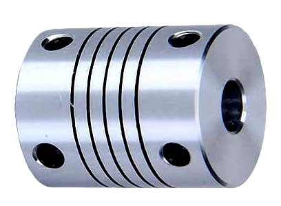
- Flexible Couplings: Flexible couplings, such as jaw couplings or elastomeric couplings, can handle both angular and parallel misalignment. They provide some flexibility to dampen vibrations and compensate for minor misalignment.
- Universal Joints: Universal joints can handle angular misalignment and are commonly used in applications requiring a high range of motion, such as vehicle drivelines.
- Disc Couplings: Disc couplings can handle angular misalignment and provide high torsional stiffness for precision applications.
- Bellows Couplings: Bellows couplings are suitable for applications requiring high levels of parallel misalignment compensation, such as in optical equipment.
It is essential to consider the torque and misalignment requirements of the specific application when selecting a motor coupling. Properly matching the coupling’s capabilities to the system’s needs ensures efficient torque transmission and helps prevent premature wear or failure due to misalignment issues.
“`
Specific Safety Precautions When Working with Motor Couplings
Working with motor couplings involves handling mechanical components and power transmission systems, which can pose certain safety risks. It is essential to follow specific safety precautions to prevent accidents and ensure the well-being of personnel. Here are some safety measures to consider:
1. Lockout/Tagout Procedures:
Prior to any maintenance or installation work on motor couplings, follow lockout/tagout procedures to isolate the power source and prevent accidental startup. This ensures the motor and equipment are de-energized, reducing the risk of electrical hazards.
2. Personal Protective Equipment (PPE):
Wear appropriate personal protective equipment, including safety goggles, gloves, and steel-toed shoes, when working with motor couplings. PPE provides protection against potential hazards such as flying debris or pinch points.
3. Proper Lifting Techniques:
When handling heavy couplings or equipment, use proper lifting techniques to avoid strain or injury. Seek assistance if needed to lift and position larger components safely.
4. Inspect Coupling Condition:
Before any work, inspect the coupling for signs of wear, damage, or misalignment. Do not work with a damaged coupling, as it may compromise system integrity and safety.
5. Avoid Excessive Force:
Avoid applying excessive force or using tools that are not appropriate for the job when installing or removing couplings. Excessive force can lead to component failure or personal injury.
6. Follow Manufacturer Guidelines:
Adhere to the manufacturer’s guidelines and instructions during installation, maintenance, and troubleshooting processes. Manufacturer recommendations are designed to ensure safe and proper operation.
7. Regular Inspection and Maintenance:
Implement regular inspection and maintenance schedules for motor couplings and associated equipment. Identify and address any issues promptly to prevent potential hazards or failures.
8. Keep Work Area Clean:
Keep the work area clean and free of clutter. A tidy workspace reduces the risk of accidents and improves overall efficiency.
9. Avoid Contact with Rotating Components:
When the motor is energized, avoid contact with rotating coupling components to prevent injury. Ensure the system is de-energized during maintenance tasks.
10. Training and Competence:
Ensure that personnel working with motor couplings are adequately trained and competent in the procedures and safety measures related to coupling installation, maintenance, and operation.
By following these safety precautions, you can minimize risks and create a safer working environment when handling motor couplings and associated power transmission systems.
“`
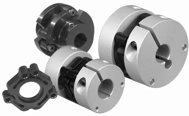
How Does a Flexible Motor Coupling Differ from a Rigid Motor Coupling?
Flexible motor couplings and rigid motor couplings are two distinct types of couplings used to connect motors to driven equipment. They differ significantly in their design, function, and applications:
Flexible Motor Coupling:
A flexible motor coupling is designed to accommodate misalignment between the motor shaft and the driven equipment shaft. It uses flexible elements, such as elastomeric materials, to provide some degree of flexibility and damping. The key differences are:
- Misalignment Compensation: Flexible couplings can handle both angular and parallel misalignment between the motor and driven equipment shafts. This flexibility reduces stress on bearings and allows for a smoother transmission of torque.
- Shock Absorption: The elastomeric elements in flexible couplings can absorb and dampen vibrations and shock loads, protecting the motor and driven equipment from damage.
- Applications: Flexible couplings are commonly used in applications where misalignment is expected, such as pumps, compressors, conveyors, and machine tools.
Rigid Motor Coupling:
A rigid motor coupling provides a solid and inflexible connection between the motor shaft and the driven equipment shaft. It does not allow any misalignment and offers a direct torque transmission path. The key differences are:
- No Misalignment Compensation: Rigid couplings do not accommodate misalignment between the motor and driven equipment shafts. Proper alignment is critical for their efficient operation.
- Stiffness: Rigid couplings offer high torsional stiffness, maintaining precise alignment between the shafts and enabling accurate torque transmission.
- Applications: Rigid couplings are used in applications where precise alignment is required, such as high-precision machine tools, robotics, and applications with low or negligible misalignment.
The choice between a flexible motor coupling and a rigid motor coupling depends on the specific requirements of the application. Flexible couplings are preferred when misalignment is expected, while rigid couplings are suitable for applications where precise alignment and direct torque transmission are essential for the system’s performance.
“`

editor by CX 2024-05-03
by
Tags:
Leave a Reply